========================================================
Notes Applicable for all DDS-60 Kits ...
Max
Supply Voltage is 12V -- We had previously stated that the supply
voltage for the DDS-60 card could reach as high as 16V, making it convenient for
use with power supplies on the workbench. However, we recently discovered
that the maximum voltage stated in the spec sheet for the AD8008 amplifier used
on the DDS-60 card is 12.6V, thus we strongly recommend not using any higher
voltage than this for your application using the DDS-60. We have not heard
of any AD8008 failures when powered with a higher-than-spec voltage, but it is
definitely recommended to ensure operation of the IC within its specified supply
voltage range. We apologize for any inconveniences. [In an
earlier design of the "DDS Amp" circuitry, the designers had used a
similar op amp that was indeed spec'd for a higher supply voltage, and they
neglected to catch this difference voltage specification when changing to use of
the similar AD8008 op amp.]
U5
and R16 no longer provided in the kits
-- We removed the "digipot control feature" from the DDS-60
design since it was not operating as intended. Thus U5 and R16 are no
longer provided in the kit, nor referenced in the manual, schematic or parts
list.
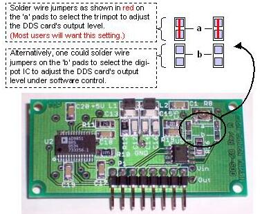
Jumpers
on pc board -- Users must be sure to place jumpers on either the 'a'
pads on the top side of
the pcb, as shown in the photo below. These jumpers connect the proper feedback resistor in the first RF
amplifier section.
Reference
Oscillator U8 or U4 ?? -- There is a typo in the Assembly and Manual at
Assembly step #8: "Attach oscillator U8 with notched end 'up' ". The
reference oscillator is, of course, U4. (There is no U8 in this
project!) The quick assembly sheet also instructs the builder to U8 and
that should also be 'U4'.
R19
and C5 shown reveresed in photo -- R19 and C5 can actually be
installed in either position - they are electrically equivalent and it was just
my goof in assembling my board used for the photo.
C4 and R7 not installed in the photo?? -- For
optimum performance, C4 and R7 should not be installed. Keeping them off
extends the "flatness" out a bit farther, resulting to a better signal
for us. (It won't harm anything if the
components are in place, but you should take them off for the best possible
frequency response performance.
Back
to the DDS-60 Kit page

Material
and concepts presented on The American QRP Club (TM) website is Copyright 2003-2006 by The American
QRP Club, Inc.
These pages are designed and maintained by George Heron, N2APB
Page Last Updated: July 30, 2006