-
Parts Inventory -- Make
sure you have all parts shown in the various items picture
above. Note that you might not have purchased some of
the options.
-
PCB Preparation -- Using
a fine-blade hack saw (or equiv) to cut out the "X" areas in
each corner of the pcb to allow it to fit into the
enclosure. Be careful to cut "on the inside" of the
lines for the corner between J7 and J2 so you don't
accidently cut the nearby trace on the bottom-side.
-
Attach Connectors -- J1 (power), J5 (keyboard), J6 (serial),
J12 (2x20 display connector), and J8 (28-pin IC socket for
U1). Note that J5 may have a metal shell, which fits
into available holes.
-
Attach Power On/Off Switch --
S1 must be mounted straight (perpendicular to board edge and
flat against it.
-
Attach the 5V and 3.3V
"voltage regulator" components (caps too) -- 5V VR1 ("462NL53B"),
3.3V VR2 ("ZLDO17-33"), C8, C9, C10, C11, C12 and C13.
Note that the "negative" side of the electrolytic tin cans
are indicated with a black stripe. Be sure you have
the orientation/polarity correct, and especially for C13,
which is oriented differently from the others.
[NOTE: For best heatsinking be sure to
solder the large tab of the VR2 package to the pad on
the PCB.]
-
Test Board Voltages --
Apply power to the 2.1mm coaxial power connector J1 and
press the S1 switch "in" to turn the board on. Measure
12V, 5V and 3.3V at the respective marked test point (pads)
near each regulator. Do not proceed until you ensure
that you have the specified voltages on the test pads.
-
Attach U2 and U3 Integrated
Circuits -- Carefully noting the pin 1 location for each
IC, insert and solder U2 and U3 (the 20-pin ICs).
DO NOT yet install U1 (the pre-programmed
28-pin dsPIC controller).
-
Attach Q1 "2N7000" --
This TO92 package with its 3 leads on a "cardboard strip" is
a MOSFET transistor. Be sure to handle with anti-static care, form the leads to fit into
the offset pad locations, oriented with the flat side of the
transistor as indicated on the silkscreen.
-
Attach All Remaining Parts --
Be careful to note polarity/orientation of the small SMT
parts.
-
Attach 4 PCB Mounting
Standoffs -- Using the parts from the Enclosure Hardware
bag, attach the four aluminum standoffs on the bottom side
of the pcb, using the short 2x56 (smaller thread) screws.
-
Attach 2 Display Mounting
Standoffs -- Using the two, shorter 4-40 threaded
aluminum standoffs to the top of the pcb next to J2 and J3
BNCs.
-
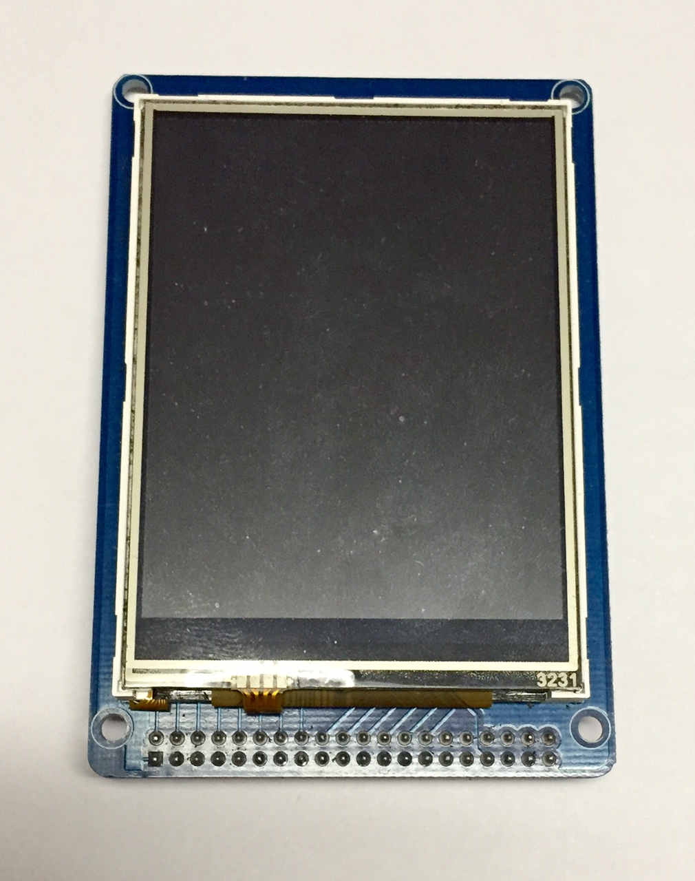
Attach U5 to Bottom of QVGA
Display -- Noting orientation of pin 1 on U5 (256 Kbit EEPROM), attach to the IC1 position on the bottom of the
QVGA Display.
1. Check
DC Levels ... Before
installing the dsPIC microcontroller and display module,
turn on power and ensure that you measure 5V and 3.3V on the
respective test pads (thru-holes) next to VR1 and VR2.
Do not proceed until you see these correct voltages.
2. Install
U1 and Display ... With the power switch OFF again, install
the pre-programmed dsPIC processor U1 and the QVGA display module, making sure the display
connector is properly lined up with the connector on the PCB. Do not install the
GDT assembly in its enclosure
until completing all the steps in this guide.
3. Power
up sequence ... Insert the SD card in the slot on the
bottom of the display, plug in the keyboard, and then press
the pushbutton to apply power. You should see the following
sequence:
a) Splash
Screen ... After
a pause of up to five seconds, you should see the splash
screen showing the firmware revision level and other
information about the GDT.
b) Beep
...
The
splash screen will be displayed for about 3 seconds, the
Satellite Display screen will show and the speaker will
beep. If you are using the optional PS2 keyboard,
you will also see the LEDs on the keyboard flash twice.
c)
The GDT has
three main modes -- The GDT modes may be selected by
tapping the Menu 'button' at the bottom of the display.
1) GPS Satellite Display -- When
connected to a GPS receiver with its antenna in a
sky-accessible location, the GPS satellite display
screen will begin showing the 'birds' and their signal
strengths. A normal one-second 'pulsing' of the screen
will be noticed each time that the data is refreshed.
After a few minutes the screen's "Fixed" field will
indicated "3-D fix", meaning that the GPS receiver is
locked onto the current time and location as received
from the satellites. (NOTE: See "GPS
Receiver Interfacing" below for details about connecting
your favorite GPS receiver.)
2) Clock Display -- This mode display a constant
indication of the 'locked' GPS time (UTC and local) as
well as the date. This is an easily-viewable and
accurate clock for the radio bench.
3) Terminal Data Entry --
It is
not necessary for normal use, but you may navigate the
menus along the bottom of the screen by using a PS2-
keyboard. You'll need to ensure that the Scroll
Lock is 'on'. (Press and
release the Scroll Lock key on the keyboard and
observe the Scroll Lock LED turning on, indicating
successful two-way communication has been established with the keyboard. The
Caps Lock and the Num Lock keys and their
associated LEDs should also be working.) See the
Reference Manual for full menu navigation and usage.
4. Mounting the PCB Assembly (PCBA) in the Enclosure ...
Now that
everything is working, you can mount the GDT in its
enclosure by carefully angling the PCBA into the milled
enclosure. It may help to push in the S1 power switch
so it doesn't stick out quite as much, thus giving you a
little more room. Use the four remaining 2-56 screws (7/16")
to attach the PCBA through the four holes on the bottom side
of the enclosure. Some "compliance" was designed into
the mounting arrangement to allow you to slightly adjust the
position of the PCBA. Start by loosening the four pcb
mounting screws on the top of the board, then loosely screw
in the four longer screws on the bottom of the enclosure.
Align the PCB so all connectors and switches protruding from
the sides of the enclosure are centered within their cutout
areas, then carefully tighten down the eight screws that
hold everything together.
5. Attaching the Front Panel Overlay ...
Apply strips of double-sticky tape around the backside
perimeter of the laminated Overlay. (Scotch brand
"Scrapbooking Tape" p/n 34-8700-9324-1 is perfect, but any
double-sided tape, rubber cement or glue works well too.)
With the enclosure lid screwed in place, carefully place the
Overlay on the front panel, ensuring that the four holes in
the corners are aligned over the four black screws that
mount the lid to the enclosure body. Firmly press down
on the Overlay (where the tape/glue is beneath) to ensure a
sufficient adherence to the plastic lid.
6.
Calibrating the Touch Screen ... Once you
have mounted the GDT in its enclosure and verified
everything is still working, let's calibrate the touch
screen.
a. The
calibration function is started by touching-and-holding the touch screen
when power is first turned on.
b. When
you see "TAP EACH CROSS" displayed, stop touching the screen
and the first cross will be displayed.
c. Touch
the center of the cross with a stylus. This is best done by
touching the screen and dragging the stylus to the center of
the cross and then raise the stylus. The GDT records the
last point touched before raising the stylus.
d. After
the each cross has been touched, another cross will be
displayed. Touch each in sequence until all nine crosses
have been displayed and touched.
e. After
the last cross have been touched, the display will change to
a simple Etch-A-Sketch screen with two buttons at the
bottom. Use your stylus to draw on the screen and see how
close the drawn line follows the point of your stylus.
f. If you are satisfied with the touch screen calibration, touch
the EXIT button and the GDT will save the calibration data
in EEPROM and start normal operation.
g. If
you are not satisfied with the touch screen calibration,
touch the REDO button and the touch screen calibration
sequence will restart.
7. GPS Receiver
Interfacing
... The GDT's serial port operates using 3.3V digital
signal levels and it will be necessary to match that
interface to that of your GPS receiver's serial stream.
Many receivers use RS232 for the serial data stream carrying
the NMEA data. In this case you will need to use a
TTL-to-RS232 converter (male
or
female) to match those data levels. If you are
interfacing to a GPS receiver having a USB port, the
common
CP2102 converter will work well. With either
interface ensure that the jumper is set for 3.3V operation
with the GDT. You may also need to Set the Baud for
your GPS receiver. Many receivers operate at 1200
baud, which is the default setting for the GDT; but if a
different data rate is needed you may adjust it using the BAUD RATE
menu. See the Reference Manual for instruction on
doing this.


.JPG)