Palm-Link908
![]()
AA908 data
collection and graphing software
for the Palm PDA
|
|
Palm-Link908
|
|
Ron Pfeiffer, N1ZSW has created a Palm PDA software program to control and plot scan data of Antenna Analyst. Just connect the Palm to the Micro908 and control it just as done in the Link908 program for the PC.
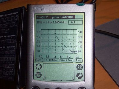
Palm-Link908 is a software program that gets installed on your Palm PDA and presents a screen like the one shown below to display the SWR, Resistance and Reactance data collected by the AA908 during a scan. You can select to view SWR, Resistance, Reactance, or all three!
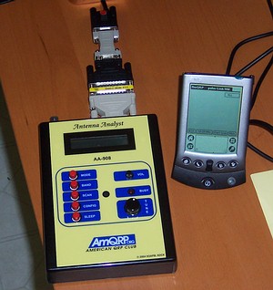
Palm-Link908 Program running on a Palm Vx (left) and a later version on a Palm IIIc (right)
(Click any photo to see full size image)Understanding the Palm-Link908 Screen
The screen capture above shows the results of a 1-10 MHz scan on an N2APB antenna that is resonant at 8.7 MHz.
Although the plot is a tad hard to see clearly on the PDA screen, you will see the same three distinct regions of the scan as on the PC version of Link908:
The "active" region from about 5 MHz to 10 MHz shows the SWR, Resistance and Reactance curves changing in relatively smooth manners, as would be expected as resonance is approached. You see the SWR curve showing a minimum at the resonant frequency, while the Resistance curve indicates close to 50 ohms and the reactance is close to zero
The "inactive" region from 1 MHz to about 5 MHz for Resistance (or to about 4 MHz for Reactance) are the frequencies where the impedance is greater than 600 and the R & X values are not able to be computed properly by the Micro908. So the instrument produces "zero results" at these points where "Z>600" is seen on the LCD display.
The "intermediate" region with the jagged transitions is where the impedance is approaching the Z>600 condition and the readings start to get out of range. This is normal and to be expected, as with most other forms of instruments approaching its range limitations.
Cabling:
Connection of the Palm PDA to the Micro908 can be a little tricky if you're not used to these things. In a nutshell, you need to connect by means of a "null modem", which swaps the data and control lines. Further, the standard Palm data cable used on the cradle or even the standard data cable is a 9-pin *female* connector ... same as that on the Micro908. Hence, you'll need a "gender changer", which is a male-to-male converter, or a cable with two male ends. The technique I used is shown below ... although a bit clunky, it works. There are some dedicated "gender-changing null modem adaptors" out there that would do everything in one small connector ... we'll find a vendor & part number for this.Here's an easy homebrew solution to this unusual connection need. Paul M1CNK made an adapter from two
9-pin male connectors plus some 3mm PCB spacers. The connections are:
pin 2 to pin 3
pin 3 to pin 2
pin 5 to pin 5
.jpg)
Custom adapter made by Paul, M1CNKBut if you don't have those two DB9M connectors handy, you could try the following ...
This is my starting point for connection to the Palm Vx. It is the standard "cradle" that holds the PDA when connected to the PC during the data sync process. Most Palm PDA owners are familiar with this device, although the exact type differs from PDA model to model. But all of these cables terminate in a female RS-232 connector (unless you have a USB version, in which case you are out of luck for direct connection to the Micro908).
The first step is finding a "null modem" converter that swaps the data and control lines. This little adapter has a male connector on one end and a female on the other.
So the next step was to get a male 9-pin connector on each end ... I had some 25pin-to-9pin adapters that allowed me to use a 25pin male-to-male "gender changer" in between them. This is the thin yellow adapter above.
And here is the complete setup. Again, although a little clunky, it does work. A simple, small 9pin male-to-male null modem connector would really fit the bill nicely ... sort of like Mike WA6FXT's setup below!
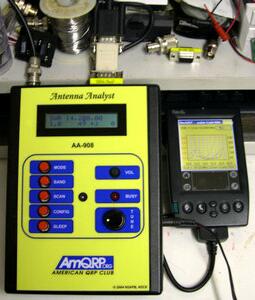
Mike WA6FXT snapped a couple of nice photos of the connection to his Palm IIIc with the simpler connector arrangement using a nul modem adapter (short white adapter) along with a 9-pin gender changer (shorter yellow adapter).
Here's a shot showing the initial screen displayed by the Palm-Link908 program. When you tap the band setting box at the bottom (currently shows "10-20 MHz"), a selection window will appear above, allowing you to select the same band as you have selected on the Micro908. Then, taping the "Start Scan" button will command the AA908 to start scanning as the Palm takes in the data sent over the serial connection.
Basic Operation:
1) Getting Started ...
a) You must have the AA908 version 4.1 (or later) software loaded. (See note in next section.)
b) The Micro908 must be connected, via a serial cable, to the Palm PDA running the Palm-Link908 software. (See description and pictures above.)
c) You must configure the AA908 to send data to the Palm PDA during the scan. That's the only way you can get data to come out of the AA908. On the Micro908, go to Config, dial up DATA OPTIONS, and select SEND DURING SCAN. Once you exit Config, this setting will be remembered for the next time you use the Micro908 AA908 software.
2) When you launch the L908 program on the Palm, a button will allow you to select the Band you will be scanning with the AA908. (Be sure it's the same Band setting as on the AA908).
3) The scan is started from the Palm-Link908 screen by tapping the START SCAN button and you will see the "Data Points" counter increment as the scan proceeds. Because of internal data buffering in the Palm, the Micro908 may complete its scan and display the lowest SWR found before the Palm-Link908 program has completed collecting the data.
4) When the scan is complete, the results will be displayed as selected in the box in the upper right corner of the screen (ALL, SWR, RESISTANCE, or REACTANCE).
5) After the data is plotted, you may select a different display mode (e.g., RESISTANCE) to see just that selected data set displayed.
Software
You must download and install the latest version of the AA908 software on your Micro908 in order to take advantage of the Link908 capabilities. This simple process is the same as you've previously normally done when downloading/installing updated software. Use the Latest Software links located on the Micro908 home page
You will need to download the Palm-Link908 prorgam and install it onto your PDA in the same way as done with other programs ... just place the plink.prc file into your Palm Desktop "Add-On" folder on your PC, then sync your PDA to your computer to transfer that file over to your PDA.
Latest Capabilities: V1.1 ...
1. Fixed 80M byte sent to AA908 from band button.
2. Added version # on top line.
3. Added timestamp to scan files.
4. Tried to speed up scan processing.
5. Send scan data to pc/LINK908 has been made consistant.
Now have Palm->PC and PC->Palm.
6. I can only display 120 of the 900 datapoints. I have added a plot mode
button on bottom right where the old plot button was:
a. "Norm" displays original full scale.
b. "AR" displays the "active region" only, or my version of it.
c. "SWR"displays an expansion of the frequency range around the low SWR.
d. "Usr" expands a user chosen frequency. After depressing button when "SWR" displayed
the full "norm" plot will be presented to the user and the button will now display "Sel".
Use the stylus to pick frequency. The plot of the frequency selected will be displayed
and the button will now display "Usr".
7. Added one more decimal digit to the frequency scale so the 160 meter plot has more meaning.
8. For users who will utilize this app a lot, I have added a mini-file system. The less you have
to enter data in Palm PDAs, the better. You will still have to enter filenames when you create
a new file, but for functions that reference files, a list will be displayed for you
to select a filename. Also under the DATA main menu, a "delete" file function is added.
NOTE 1: When you first run V1.10 you will see a display that says there is no directory
and a new one will be created for you.
NOTE 2: When you start the app a line will be displayed telling you how many files are in the
directory.
NOTE 3: Mini file system has changed the format of the saved scan files and is not compatible
with older scan files. I have provided a "convert" routine found under the DATA
main menu.
9. I have decided that the firmware loader be a seperate app and will be coming soon.Version 1.0 ...
1. Found and fixed scaling problem.
2. Added cmd button upper right for future upgrade.
3. Added Note button upper right. This feature allows you to annotate your scan. This button will
display the current note. You can then edit it or leave alone. This note will be
attached to the scan data when it is saved. Upon loading the file back in for viewing the note
will be retreived with it. You are also prompted for note entry when you "save" scan
and when you start a scan. Just to remind you.
4. I deleted the Plot button as real estate on palm display valueable.
Plots are automatically plotted after: scan complete, load file complete,
or change display say from ALL to SWR.
5. Added time in top right bar.
6. When a display is present I have feature similiar to Link908. Press the stylus down in the
plot area and the 3 variables will be displayed in the upper left as long as the stylus is depressed.
The values displayed will be associated with the "x" coordinate so you do
not have to press on any display line. Just place the stylus on the "x" coordinate(
frequency). After you remove the stylus the values are removed and the original low SWR data is
displayed. NOTE: Sometimes after a button is used the first depression by the
stylus will NOT get a display, just pick up stylus and place it down
again and the values should be displayed.
7. Put code in to throw away empty lines of data and limit resistance and
reactance values to no larger than 600.
More to Come!
The Palm-Link908 is an evolving project ... more capabilities will be added as time goes by.
1) Right now the ability is present to collect the data from the Micro908 over the serial port simultaneously when the instrument is scanning. Later, when the capabilities are present in the Micro908 to store the scanned data to local SEEPROM memory, the Palm-Link908 program will be able to load and display that saved scan data.
2) Remote Control of the Micro908 AA908 instrument will be possible when another screen gets activated in Palm-Link908. Later on, when pressing the Remote Control button, another screen will present buttons to set Configuration, select modes and a display area will act as a "remote LCD display" so you can control the instrument from your PC keyboard and see results right on the screen!
Support
Ron N1ZSW and George N2APB are available on the Micro908 reflector to answer questions about installation and operation.
Again, thanks very much to Ron for his self-initiated contribution to the Micro908 project!
![]()
Page Last Updated: April
17, 2005


.jpg)
.jpg)


