About the
AmQRP Club
Frequently_Asked_Questions
Kits
Projects
QRP Forums
Contesting
References
Links
|
|
|
About the
AmQRP Club |
Keyboard Connector Mod
I messed up the layout for the keyboard connector J11 on the Micro908 motherboard. We haven't had occasion to use it until now, but we're getting the PSK31 software ready for deployment now and users will need to modify the traces for the keyboard to be plugged in and work.
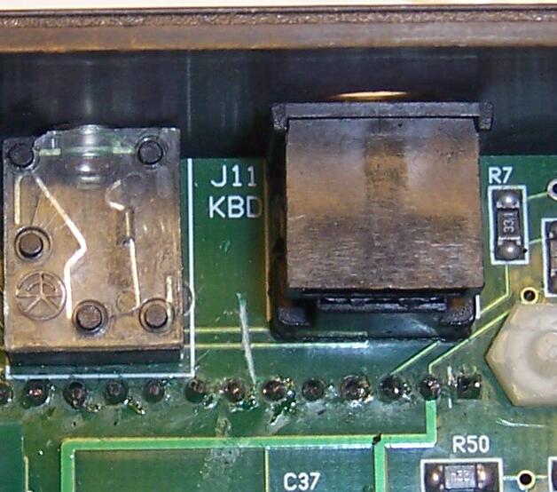
Here's the numbering for the 6-pin mini-DIN connector we use as J11 on the motherboard
.gif)
|
|
|
|
|
|
|
|
|
Modification Steps
1) Isolate pad #4 from ground. Using a sharp-pointed razor knife, carefully cut the four "spider traces" connecting the pad to the ground plane around the hole. Check with a VOM afterwards to ensure you completely isolated the pad from ground.
2) Cut the trace leading away from pad #6. Again, measure to ensure that you have isolated this pad as well.
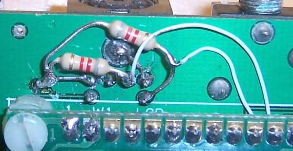
3) Add jumper from pad #4 to the pad directly to the left. (This is 5V.)
4) Add jumper from pad #3 to the larger GND pad above-left of it.
5) Add resistor from pin 1 to the 5V jumper added in step 3 above. (Resistor can be any convenient value between 1K and 10K.)
6) Add resistor from pin 5 to the same 5V jumper added in step 3 above. (Resistor can be any convenient value between 1K and 10K.)
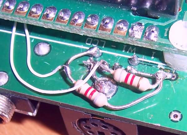
7) Add jumper from pad #5 (it's easy to tack solder to the resistor lead) to P2 pin 34 below the LCD. (Route the wire underneath the LCD.) Although the P2 pins were nipped off, there is enough to tack-solder the wire jumper onto.
8) Add jumper from pad #1 (it's easy to tack solder to the resistor lead) to P2 pin 25 below the LCD, in the same manner as above.
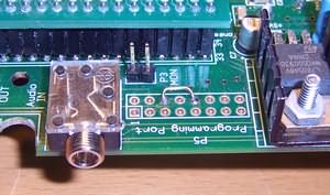
9) Now, turn the motherboard over and slice the two traces leading to the J11 connector, as shown in the photo below. This will isolate the "old" clock and data traces and allow the "new" traces (i.e., the jumpers) to deliver the signals properly.
10) And lastly (whew!), all you need to do is add a jumper from pad 6 to pad 10 on the Programming Port P5. This connects the Kbd Clock line to the IRQ interrupt line on the HC908 controller ... which completes the mods!
TEST SOFTWARE
We've added a DIAGS menu item to the Config menu of the AA-908 software, version 6.0g. Within the DIAG menu there is a Keyboard Test function that will echo typed keys to line 2 of the LCD.
1) Download AA_60g.s19 to your computer from here. (The source is available here too, in case you are interested.)
2) Load this latest AA908 software to your Micro908 in the standard way. (Use TeraTerm to Load Software.) ** Don't forget to select Default Settings in the Config menu immediately after loadingthe software. This ensures that the nonvolatile memory on the HC908 controller is synchronized with the new software just loaded.)
3) AA9089_v60g is the full antenna analyzer software program. You can keep it loaded long-term and use it like normal. Just remember to recalibrate before using.
4) To test the keyboard ... press the Config button and select the new Diagnostics menu (turn the dial one menu iten counter clockwise).
5) Then select the Keyboard sub-menu item (Turn the dial two positions CCW.)
6) See "Keyboard Echo" displayed on the top line of the display. If your mods were done properly, you should see characters appear on the second line of the display when you press keys on the keyboard.
Good luck and lety me know how it works out for you.
~George N2APB
![]()
![]()
Page last updated:
December 16, 2007