 |
Introducing Version 3 firmware and the ...
Network Analyzer Controlling Terminal

NACT = NAT Version 3 Software, plus a few easy hardware mods, enabling some terrific new capabilities!
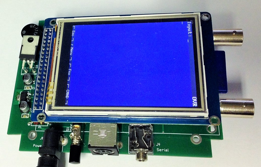

Up to now, the Network Analyzer Terminal (NAT) has relied on the PHSNA controller to do most of the grunt work of interfacing the Device-Under-Test and the RF Power meter. Version 3 changes that; it eliminates the need for the PHSNA controller. The RF signal source is generated by an on-board, high-quality DDS-60 card. The output of the RF power meter is fed directly to an ADC port on the NAT to be interpreted and translated to dBm by the V3 firmware. A very simple modification to an existing NAT pc board adds two BNC connectors to accommodate these two signals. After making this modification and loading V3 firmware, the NAT is no longer just a Network Analyzer Terminal, but instead it has become a Network Analyzer Controlling Terminal (NACT). Version 3 firmware has retained all the functionality of theV2 NAT can still be operated with a PHSNA controller as a V2 NAT.
Background ...
Firmware Version 1 introduced the Network Analyzer Terminal (NAT) as a replacement for the PC in a Poor Ham’s Scalar Network Analyzer (PHSNA). The V1 NAT can operate in both Terminal mode and PLX modes. In Terminal mode, the NAT emulates a terminal emulator app, in PLX mode it emulates an Excel spreadsheet running the PLX-DAQ macro. This version relies on a PHSNA Arduino microprocessor-based controller to control the PHSNA RF source and translate the RF power meter readings to meaningful data. This version will run with the standard PHSNA controller firmware but runs better with a version of the PHSNA firmware that formats displayed text (including menus) for the NAT display.
Firmware Version 2 added two significant enhancements: Touch Screen operation and Signal Generator mode. Using the touch screen without a keyboard, a V2 user can do essentially all the functions possible with V1. This version also introduced Signal Generator mode whereby the user can directly control the RF frequency as he would with a stand-alone signal generator. In Signal Generator mode, the NAT also displays the RF power meter readings. This version will also run with the standard PHSNA firmware but there is a modified version of the PHSNA firmware that not only improves the appearance of the display but offers more functionality and better performance than the standard, unmodified firmware.
Firmware Version 3 now brings on some exciting new capabilities. Read on!
Version 3 Firmware Features:
Version 3 firmware retains all Version 2 functionality plus adds several new features, many of which do not need the NACT modifications such as:
Remote control using the Windows app
Direct file transfer to a PC (UPLF and UPLD DOS commands)
Improved DOS file and command selection from the touch screen
Calibration constants saving to and restoring from EEPROM
A number of minor enhancements and bug fixes.
Additional Features:
Provides all PHSNA controller functions;
Significantly improves performance (typically more than two sweeps per second in auto start mode);
Supports calibrating the RF Power Meter (slope and intercept);
Provides DDS reference clock calibration;
Enhances and simplifies handling of calibration data;
Stores calibration data in EEPROM with restoration at power-on;
Uploads spooled data directly to a PC terminal application;
Uploads spooled data directly to Excel with the PLX-DAQ macro running; and
Provides remote control in Signal Generator mode enabling operation with the Windows app developed by Nick Kennedy, WA5BDU, including the generation of Morse code to help identify the RF signal in a receiver.
Documents:
NAT User Guide Extension for Version 3 ... Also includes NAC-to-NACT Upgrade Instructions
Software:
Version 3 hex file ... Right-click and save to your computer. Unzip and then place the hex file onto a SD Card. Insert SD Card to the NACT and use SDLD command to bootload new software onto the NAT.
Tutorials
0: Reference Clock Calibration
This tutorial takes you through the steps to calibrate the reference clock which is a prerequisite to virtually all NACT operations.1: RF Power Meter Setup
This tutorial takes you through the steps to setup the RF Power Meter interface signal levels to interface with the NACT ADC. This procedure should be performed before using the NACT to avoid exceeding the maximum voltage specification for the NACT’s dsPIC micro controller.2: RF Power Meter Slope and Intercept
This tutorial takes you through the steps necessary to determine and save the slope and zero intercept point for the RF Power Meter power curve. This procedure should be done before using the NACT for DUT testing to assure the accuracy of the power level readings (dBm).3: Frequency Response Calibration
This tutorial takes you through the process of generating and capturing calibration data to account for variations in of the DDS output level at different frequencies. The calibration data can be saved in EEPROM and reloaded every time the NAT is powered up. This calibration sequence also normalizes the power readings such that they reflect the absolute power readings one would observe if the DDS were outputting a constant RF power level of one milliwatt. Some basic Signal Generator mode operations are also described.3T: Frequency Response Calibration
This tutorial takes you through the process of generating and capturing calibration data to account for variations in of the DDS output level at different frequencies using only the touch screen. The keyboard is not used. The calibration data can be saved in EEPROM and reloaded every time the NAT is powered up. This calibration sequence also normalizes the power readings such that they reflect the absolute power readings one would observe if the DDS were outputting a constant RF power level of one milliwatt. Some basic Signal Generator mode operations are also described.4: Measuring DUT Frequency Response
This tutorial takes you through the steps necessary to perform frequency scans on a basic DUT (Device Under Test). A “basic DUT” is one that does not require a test fixture and can be inserted directly into the test setup between the DDS output and the RF Power Meter input. Basic DUTs include RF filters, RF cables, attenuators, etc. The tutorial also covers the plotting, spooling, and playback of the scan results.5: Crystal Characterization and Matching
This tutorial takes you through the steps to test, grade, and sort a batch of crystals to select one or more groups of crystals for use in a crystal filter. The sample filter used here is the 6-crystal filter used in the PHSNA Measurement Receiver designed by Jerry Haigwood, W5JH, and implemented and kitted by Jim Giammanco, N5IB (https://groups.yahoo.com/neo/groups/PHSNA/files/Measurement%20Receiver/ ). The principles demonstrated in this tutorial could be applied to most any other crystal filter design. The object of this tutorial is to analyze a batch of 30 crystals to identify the six crystals with the minimum series resonant frequency variations or “spread”. If we are lucky, we will be able to identify more than one group of crystals with acceptable frequency spreads. The crystals used here were ordered as 3.2768 MHz and are all marked “3.27” (Mouser Part no. 520-HCA327-17X).6: Return Loss Bridge
This tutorial takes you through the steps to use a Return Loss Bridge (RLB) to measure the return loss and VSWR of a resonating DUT.
Copyright 2014 Midnight Design
Solutions, LLC. All Rights Reserved.
Page last updated: Oct 5, 2014