PicoMite Memory Keyer

DOCUMENTATION
Assy & Operation (v2.11) (25-Aug)
Parts List (PDF)
or
Online via Mouser
(Order individual parts
online or you can order all projects at once by clicking "Buy Project"!)
COHERENT
CW Research Project
An extreme
low-power CW communications mode that enables one to copy signals down
to, and below the noise floor. Hardware based on K1SWL PMK using
shields shown on this page.
SOFTWARE
PMK v3.12 NEW
Keyer status and date/time displayed on optional OLED and GPS cards on shield. Based on PMK v2.11 thread. See pic of display! And here's the description. "Backward compatible" ... Keyer works fine with this software even if shield or OLED and GPS cards not present! ... n2apb
Simple demo program using GPS board to acquire and display date & time to OLED.
Program the PMK using MicroPython! - by Steve N3SB
SHIELDS
APP NOTE #1: Adding an OLED Display to the PMK
APP NOTE #2: Adding a GPS Module to the PMK Platform
BUY NOW


Have you ever had a simple project idea that becomes an all-consuming affair? It was worth it, though, and the results are exhilarating!
I had recently dabbled in one of the larger CW contests and I’m by no means a ‘Big Gun’ operator. I was making enough contacts, though, such that sending an exchange over and over became pretty tedious. I do have a modern rig that includes message recording from keyer paddles and subsequent playback. The issue? Two sequential button presses are required on a menu-driven display: the first to arm the message readout and the second to start the message. I found myself not pressing the first button firmly enough and instead of that CW message going out, I was altering the rig settings. I realize that there are a number of computer-based Morse applications out there. My shack is already extremely cramped for space and is located at the limits of Wi-fi coverage, so I needed a simpler memory keyer solution.
What to do? By way of explanation, I’m a diehard homebrew enthusiast and a frugal one at that. I don’t often spring for a commercial product if I can build one for myself, so a ‘D-I-Y’ Memory Keyer seemed like just the ticket as I cast about for a new project. The way forward was unclear, though. I’m conversant with C/C++ in the Arduino environment and it was time for a change.
I discovered that the Raspberry foundation recently announced an offering dubbed the Raspberry Pi ‘Pico’. Its tiny single-board computer module measures only 0.85 by 2.0 inches (2 x 5 cm) and has some really interesting features. Free software for this device includes the MMBASIC interpreter and there’s plenty of memory space. With the interpreter loaded, it’s referred to as the ‘PicoMite’. Best of all, Raspberry is selling the Pico module for only about $4. I was hooked right there!
K1SWL
PicoMite Memory Keyer (PMK)
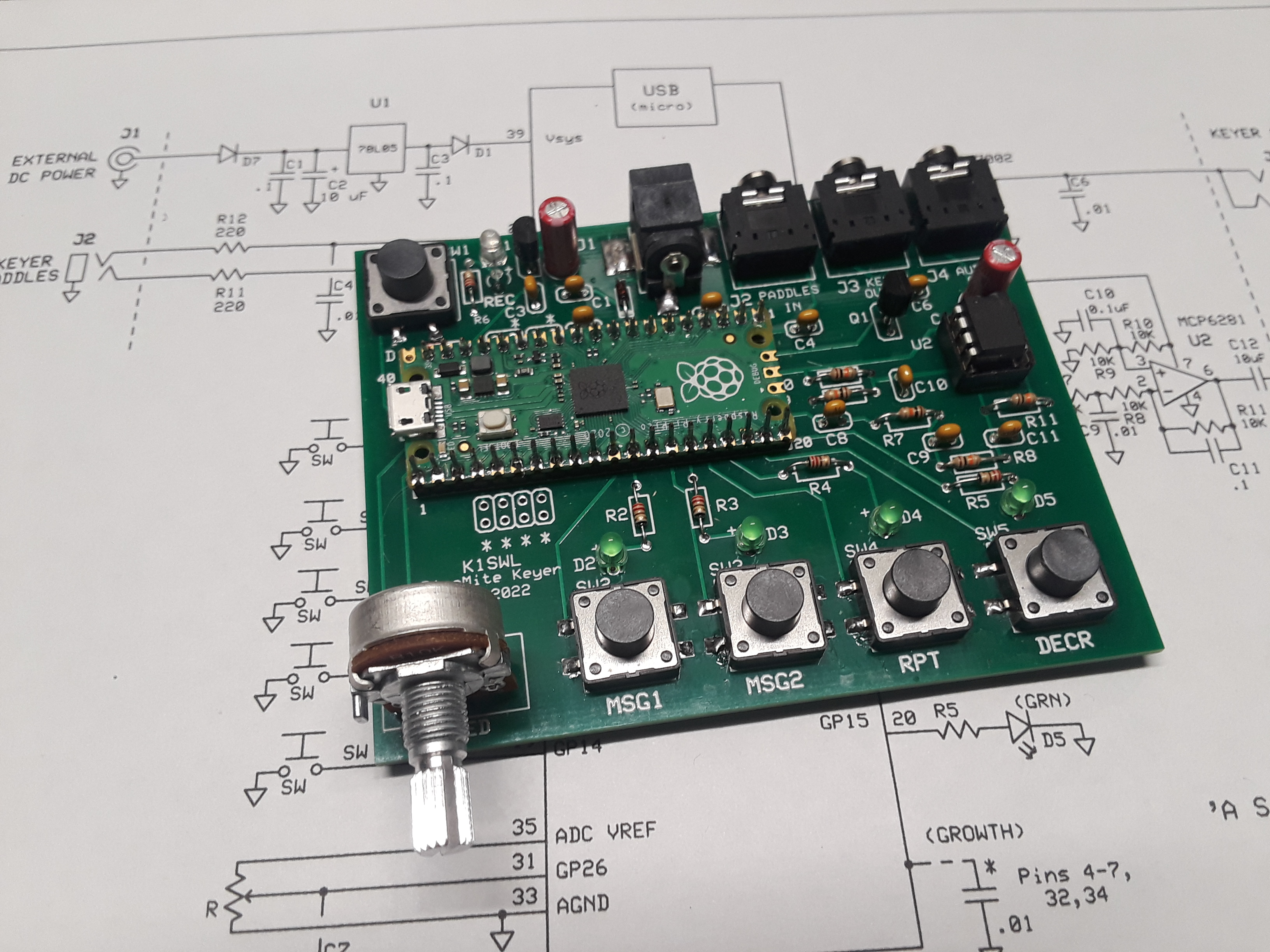
Schematic:

(Download Schematic)
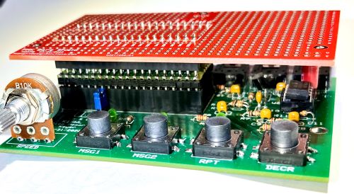
Hardware Layout:

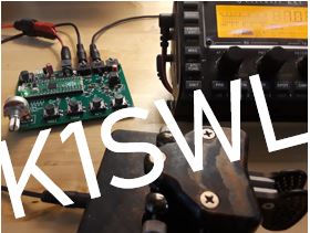
PMK 'in action' on the bench!
(Click image for full-res view)
PMK Expansion Boards: "Shields"
"Shields" ... What a great way we have these days to extend a microcontroller board's capabilities and customize its features for a given application! Such is the case we have provided for the K1SWL "PicoMite Memory Keyer". The PMK already has a rich and flexible base hardware I/O -- meaning that it has pushbuttons, I/O jacks, LEDs, potentiometer, sound output and an incredibly powerful and inexpensive microcontroller that may be programmed using numerous languages to perform designated tasks. Now we literally add on top of all this a "shield" expansion board to provide hardware to allow hams the ability to customize all this power for their own projects and applications.
At this time we have three Shields available for this customizable expansion to the K1SWL PMK platform:
Shield 1 is a bare prototyping board that plugs onto the PMK's Pico microcontroller and provides access to all its signals. Design and solder your own circuits onto this open plugboard and bring your new application to life!
Shield 2 is a board that has three very popular hardware peripherals already "wired" on the pcb with software libraries available to run them: the popular 128x64 OLED display (16 text characters x 5 lines); an inexpensive GPS receiver board to provide accurate timekeeping and delivery of time-precision interrupts as-needed to the Pico; and the extremely popular Si5351 synthesizer clock board from QRP Labs, providing up to three RF frequencies for use in local oscillators, VFOs, and more. Shield 2 is a very powerful plug-in to the K1SWL PMK.
Shield 3 is a two-part RF deck that serves (first) as a 40-meter QRP CW transceiver with the PMK serving as the keyer and radio controller. The transmitter circuits are on the main shield pcb and the superhet receiver plugs on the shield atop three connectors around the edge. (This shield is still in development but is expected to be ready for the FDIM Seminar and Dayton Hamvention in May.)
N2APB

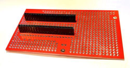
PMK Shield 1: Prototyping Board
Note below how this red shield plugs on the top of the Pico processor to extend the I/O signals up to the top board for customized expansion circuitry. (Connectors are detailed under "Shield 2".)
I’ve attached some photos of an as-yet undisclosed project that requires more horsepower than can be supplied by the Pico, yet still using the fine array of I/O offered by the PMK. Being developed deep within a hidden bunker beneath a non-descript building in East Tennessee, I’ve soldered long-lead, double-ended pinheaders to the bottom of Shield 1 such that it plugs into the empty Pico SOCKET, thus elevating the shield over the PMK-board-without-Pico and extending all the I/O components connections and power+grounds up to the shield pcb. Then on that pcb, I’ve attached a Teensy 4.0 processor, offset slightly from the Pico footprint, and a larger TFT display. The Teensy 4.0 chip will then be wired to the PMK’s I/O pins as-needed for the new project.
So … Instead of just taking a project (like the PMK) and adding a shield to modify/add capabilities, what I’ve done is flip the model by taking a project already replete with established I/O capabilities and I’m doing a brain transplant with a shield to enable another project with way-souped-up performance.


The "T4 Shield" (See description above)
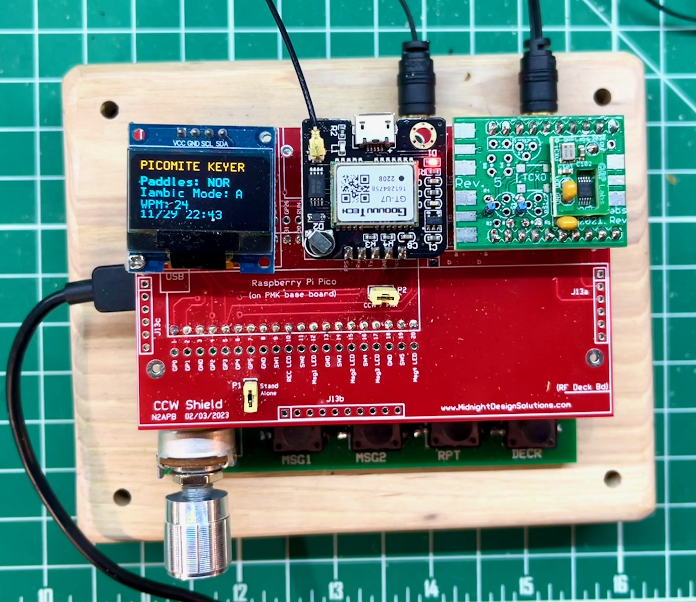
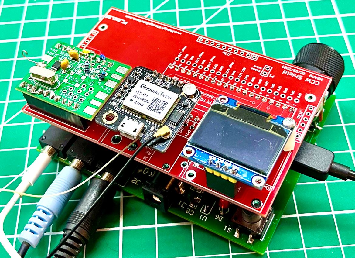
PMK Shield 2: OLED-GPS-CLK
Provisions are made for adding an OLED display, a GPS receiver and the QRP Labs' Si5351 Synthesizer to the PMK for your custom hardware and software projects! Plugs into the Raspberry Pi Pico processor on the PMK base board and provides full access to all the used/unused pins for an inexpensive-yet-powerful projects for radio projects.


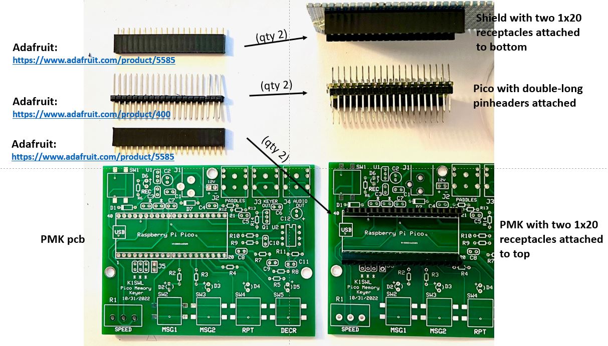
Pinheaders & receptacles for the Shields to mount on top the Pico controller
APP NOTE #1: ADDING an OLED DISPLAY to the PICOMITE KEYER
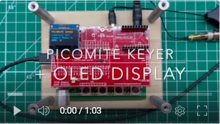
Here’s a short "application note" describing how you can add a nifty little OLED display board to the PMK to display paddle modes and the speed dynamically in WPM as you adjust the SPEED control on the PMK base board. Pretty handy capability to have while operating on the air!
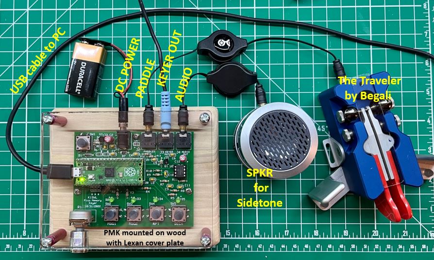
Here’s what it looks like when complete (left) … as well as a short YouTube demo video (right) showing how the SPEED control and display work together.

.jpg)
.jpg)
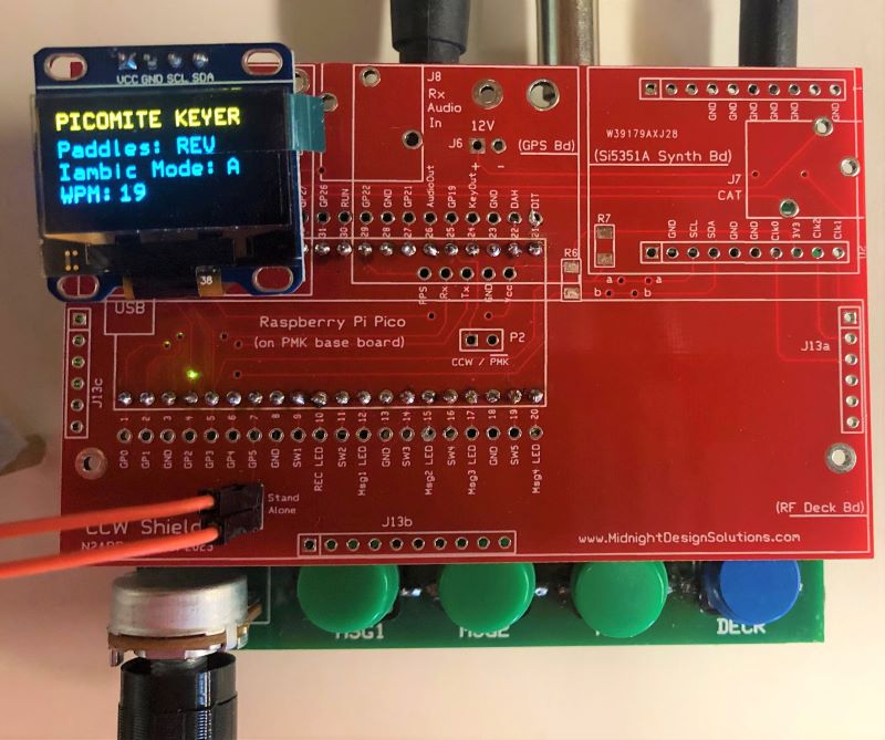
Nice shots of the PMK-OLED v1.0 display
showing interactive status & keyer speed.
Note the nice job Tom did on his protective Lexan cover and base.
(Click on photos for full-res view.)
(Photos courtesy of Tom VE3NY)
So all you need to do this is … Get yourself an i2c 0.96” OLED board like the one below and plug it into the Shield 2 board. (Be sure to get the OLD board type that has VCC on the outer edge of the 4-pos’n connector. Some have GND in that spot.) Place a jumper on the shield’s P2 connector, and load up the software file PMK-OLED v1.0 you will see the display come to life showing the paddle modes and keyer speed.
PARTS LIST
PMK Shield 2 … below!
OLED Display on eBay … 3PCS OLED Display 0.96" 128x64 Blue I2C IIC SSD1306 for Arduino Raspberry Pi
4-position SIP socket … from Mouser, two 1x20 position (cut to fit), or equiv
2-position SIP pinheader … from Mouser
(Before you RUN the program, type the following lines at the Command Prompt ‘>’, as follows:
-
Option System i2c GP2,GP3
-
Option LCDPANEL SSD1306I2C,L
APP NOTE #2: ADDING a GPS BOARD PMK PLATFORM
Here’s another short "application note" describing how you can add a GPS module to Shield 2 on the PMK board to display GPS data to the OLED display, as shown in the photo below. We use a NEO-7M GPS module that was plentiful on eBay several years ago but recently was discovered to have evaporated from that marketplace. We found some equivalents at AliExpress and several of us are in the process of getting and qualifying them for use with the PMK platform.

.JPG)
GPS Antennas
It’s helpful to get an external GPS antenna to place up against a
window if your operating position is not in an open area already. Most
GPS boards come with a small “patch” antenna that attaches by a thin
2”-long cable to the board, which is sufficient if the GPS receiver is
up in a drone or out in a field – i.e., it’s natural use. But here in
the shack I use a small, inexpensive, magnet-mount GPS antenna similar
to what we used to see on autos. It has a 10-foot (?) cable terminated
with an SMA connector. I then use a short, inexpensive jumper cable to
adapt that down to the tiny connector that plugs into the U-FL connector
on the GPS board.

Shown above is the small/short "ceramic antenna" that is sometimes provided with the purchase of a GPS receiver module. When plugged into the GPS module, it is only effective when there is a pretty clear and/or unobstructed view of the sky for adequate satellite reception and synchronization. Most often we need to use the combo shown below for an "external antenna"..
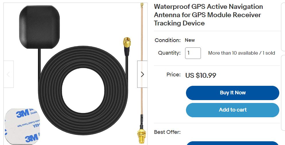
The Active GPS Antenna shown here is a nice one from eBay that has a cable allowing antenna placement about 10' away from the GPS module (and your PMK and/or operating position in the shack). This is an active antenna, meaning that it has an internal LNA (low noise amp) powered through the cable by the 3.3v supply on the GPS module. And this is also a nice package deal because it includes the SMA-to-u.FL cable that adapts the long cable to the tiny antenna jack on the GPS module. (If you get a different GPS antenna, you would need to separately find such an adapter cable.)
Purchase the PMK & Shields (bare
PCBs-only)
(Please remember to select either US Shipping
or DX shipping with your order below, as
appropriate)
| K1SWL "PicoMite Memory Keyer" PCB ($5) | ||
| Shield 1: Prototyping PCB ($3) | ||
| Shield 2: OLED-GPS-CLK PCB ($5) | ||
| Shield 3:
Transceiver PCBs ($8) Shield 3a = the OLED, GPS, Clk and Tx Shield 3b = the Rx |
(Shield 3a pcb available in January.) (Shield 3b pcb hopefully available by February.) |
|
| Socket & Pinheader
Set: for Pi Pico ($6) Two 1x20 SIP socket strips for the PCB, 0.1" spacing Two 1x20 SIP pinheader strips for the Pico module, 0.1" spacing |
||
| Socket Set for
Shields ($3) Two 1x20 SIP socket strips, 0.1" spacing |
||
| NOTE ==> | Shipping to U.S.
Destinations ($5) Must select this shipping for US purchase |
|
| NOTE ==> | Shipping to DX
Destinations ($15) Must select this shipping for DX purchase |
PayPal to: sales@MidnightDesignSolutions.com
or
Write check payable to "Midnight Design Solutions" and send to ...
Midnight Design Solutions
c/o George Heron N2APB
205 Okema Trace
Loudon, TN 37774
USA
Visitor Counter: